
block diagram of a process flow in a brewery plant

Utility Flow Diagram an overview | ScienceDirect Topics
The utility flow diagram is a type of PID that represents the utility systems within a plant and shows all equipment and piping with respect of utilities (water, air, steam, etc.). General plot plan The spacing and arrangement of the unit should be designed in accordance with .

Typical Process Flow Diagrams (PFDs) EnggCyclopedia
Typical Process Flow Diagrams (PFDs) ... Block diagram for pygas processing Pyrolosis gasoline or pygas (C5+ cut) is a liquid byproduct derived from steam cracking of various hydrocarbon feedstocks in olefin plants. This C5+ cut, if left in its raw form, has little commercial value owing to its high reactivity and low stability.
PROJECT STANDARDS AND SPECIFICATIONS piping and in
Direction of flow In general, the main direction of flow proceeds from left to right and from top to bottom. Inlet and outlet arrows are used for indicating the inlet and outlet of flows into or out of the diagram. Arrows are incorporated in the line for indicating the direction of the flows within the flow diagram.
Function Block Diagram Approach for Manufacturing Process ...
A process control language using function block diagram approach is designed for realtime control of continuous manufacturing process automation system, in which five groups of primitIVe functIon blocks and macrotype function blocks are defined to make an operator easy to implement target programs.

AUTOMATION OF A PROTOMATIC LABELLER OF A .
electrically. At Accra Brewery Limited (ABL), it is by electrical means which is accomplished by the "KRONES PROTOMATIC" labeller. Figure 1 shows a picture of a part of the protomatic labeller. Figure 1. Part of the Krones protomatic labeller The functional block diagram of the Krones Protomatic Labeller is presented in Figure 2. Figure 2.
Resources
There can be an overall (master) diagram, then particular blocks (subsystems) can be broken down into further block diagrams. The following example shows a master diagram for a manufacturing plant . This is then followed by a second diagram, which is a block for one of the systems in the master diagram.

FLOWSHEET PRESENTATION – I | Chemical Engineering .
Apr 15, 2014· As the process flowsheet is the definitive document on the process, the presentation must be clear, comprehensive, accurate and complete. The various types of flowsheet are discussed below. Block diagrams A block diagram is the simplest form of presentation. Each block can represent a single piece of equipment or a complete stage in the process..
PROCESSING OF FOODS PROCESSING
• Plant Design: the design of whole processing plant, including the processing/control equipment, the utilities, the plant buildings, and the waste treatment units. PROCESS FLOWSHEETS Process flowsheets are graphical representations of the layout and flow of equipment and materials in the plant. PBD: Process block diagram PFD: Process ...
Flow Process Control Trainer | Intelitek
The JobMaster Process Control – Flow Trainer simulates industrial plant systems found in oil gas, chemical and food production plants around the world. This training system, part of the JobMaster Self Assembly Process Plant, makes an excellent platform for training in all aspects of liquid flow instrumentation and engineering.
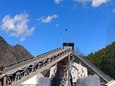
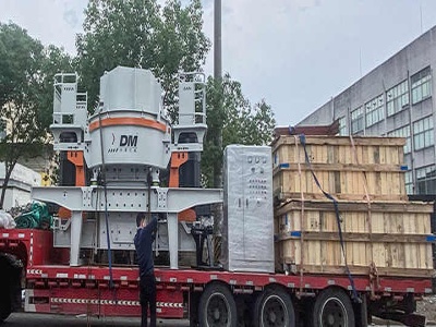
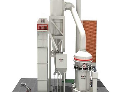
block diagram an process of cement
Kiln process cement industry block diagram cement industry process flow .. flow diagram for a wet ... Concrete Batching US EPA may be best known for its conventional 8 x 8 x 16inch block.
PFD Process Flow Diagram Online Drawing Tool
BFD Block Flow Diagram Block Flow Diagram is a schematic illustration of a major process Blueprint Letters Letters used to differentiate blueprint drawings Commissioning Commissioning is methodical procedures and methods for documenting and testing performance of a technical system
Ballast Water Treatment Plant Block Diagram
Ballast Water Treatment Plant Block Diagram ... Jump to Process Flow Diagram : NSG will start by developing a block diagram of your overall. Explain, with the aid of a circuit diagram, the operation of a synchroscope. With reference to fixed fire fighting systems employing water in fog or mist met with the

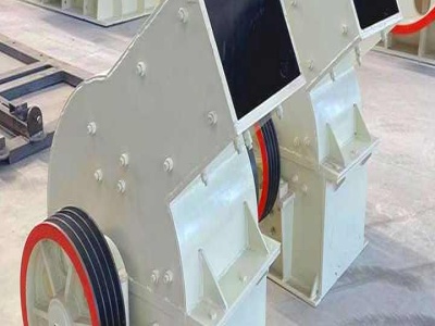
copper processing block flow diagram steps
Process Flow Diagram ... divide the process diagram in three type or step: BFD : The Block Flow Diagram Contact Supplier How copper is made material, used, processing, steps ...

Glass Industry With Process Blo0Ck Diagram
A process flow diagram (PFD) is a diagram commonly used in chemical and process engineering to indicate the general flow of plant processes and equipment. The PFD displays the relationship between major equipment of a plant facility and does not show minor details such as .

copper processing block flow diagram steps
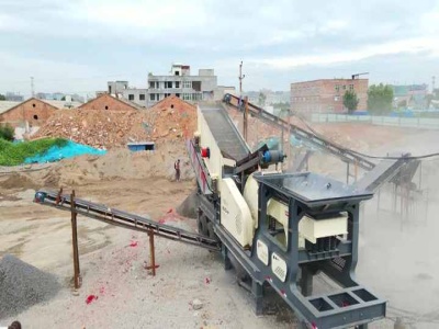
flow diagram of the mining of iron schievelavabojourdan. process of coal mining diagram YouTube coal mining process flow chart diagram,23 Jun 2015, process of coal mining diagram, of iron ore pellet plant mobile gold processing plant prices cost of magnetite ore beneficiation plant in kenya process flow of copper plant gold equipment south africa stone crushing ore mining
A process flow diagram (PFD) is commonly used by engineers ...
A process flow diagram (PFD) is commonly used by engineers in natural gas processing plants, petrochemical and chemical plants, and other industrial facilities, in chemical and process engineering.
block diagram of steel production plant
Coal will likely play a significant role in the production of that energy. .... power plants with CO2 capture or other energyintensive industrial production plants. Examples of these include iron and steel, metallurgical, hydrometallurgical, glass, cement, oil refineries and ... Block diagram of an ITM Oxygen unit in an IGCC facility.
Production of Sulfuric Acid ( Block Diagram)
The following flowchart summarises the industrial production of sulfuric acid, namely by the Contact ProcessYou can edit this template and create your own diagrams can be exported and added to Word, PPT (powerpoint), Excel, Visio or any other document.
Preparing Process Block Diagrams CAE Users
Preparing Process Block Diagrams. A process block diagram is a simple flowchart that represents an overview of the process or system. Process block diagrams are used to simplify a complex process. As opposed to a program flowchart, a process block diagram does not .
functional flow block diagrams for mineral process projects
FFBDs are also referred to as Functional Flow Diagrams, functional block diagrams, ... History The first structured method for documenting process flow, the flow process ... flow diagrams, for example: Change control flow diagram, used in project .... model can be derived directly from events' logs using process mining tools.
The Basics of Process Control Diagrams » Technology ...
A block diagram is a pictorial representation of the cause and effect relationship between the input and output of a physical system. A block diagram provides a means to easily identify the functional relationships among the various components of a control system. The simplest form of a block diagram is the block and arrows diagram. It consists of a single block with one input and one output (Figure 1A).
Crude Oil Refinery Block Diagram
Crude Oil Refinery Block Diagram Create Process Flow Diagram examples like this template called Petroleum Crude Oil Desalting Gas Separation Atmospheric Distillation Vacuum Distillation Reality: Refiners only make 515 per barrel of oil processed. The Reality of Refining: 1) PROCESSING Refinery Block Flow Diagram – Crude/Vac Units.